STM32Cube
The STM32Cube Ecosystem is a combination of software tools and embedded software libraries:
A full set of PC software tools addressing all the needs of a complete project development cycle
Embedded software bricks made to run on STM32 microcontrollers and microprocessors, that will bring various functionalities like the Flexible Safety RTOS
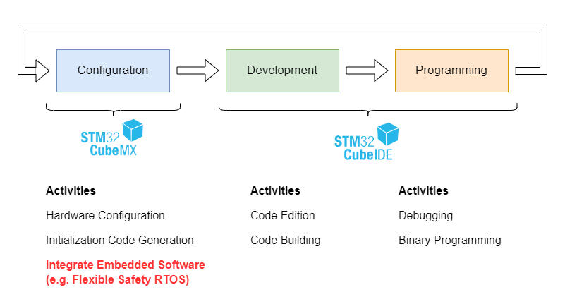
The STM32Cube Ecosystem
The embedded software bricks are integrated by adding an STM32Cube Expansion Pack to the STM32CubeMX tool. This pack file includes the additional files, integration options and simplifies the first steps into the provided software package.
Version Information
During the development of the Flexible Safety RTOS integration and the demo applications, we use the following environment for your reference:
STM32Cube MX Version 6.11.1
STM32Cube IDE Version 1.15.1
Warning
Older versions may not work as expected. To avoid this, we recommend updating your local STM32Cube ecosystem. Newer versions are most likely working.
In case of problems, don’t hesitate to contact us. The Embedded Office team will be happy to help you. Please write us your used STM32Cube MX version with your question or problem: Contact Form
Installing the Expansion Pack
The installation of the STM32Cube Expansion Pack is explained in detail by STMicroelectronics in the STM32CubeMX User Manual. The following chapter explains a simple way to activate the middleware software component Flexible Safety RTOS (FS-RTOS).
Download the pack EmbeddedOffice.I-CUBE-FS-RTOS.1.0.1.pack
In STM32CubeMX, select in the main menu bar:
Help > Manage embedded software packagesInstall it using the button
From Local ...Read and accept the Evaluation License Agreement to start the installation and close the Embedded Software Package Manager when the installation is finished:
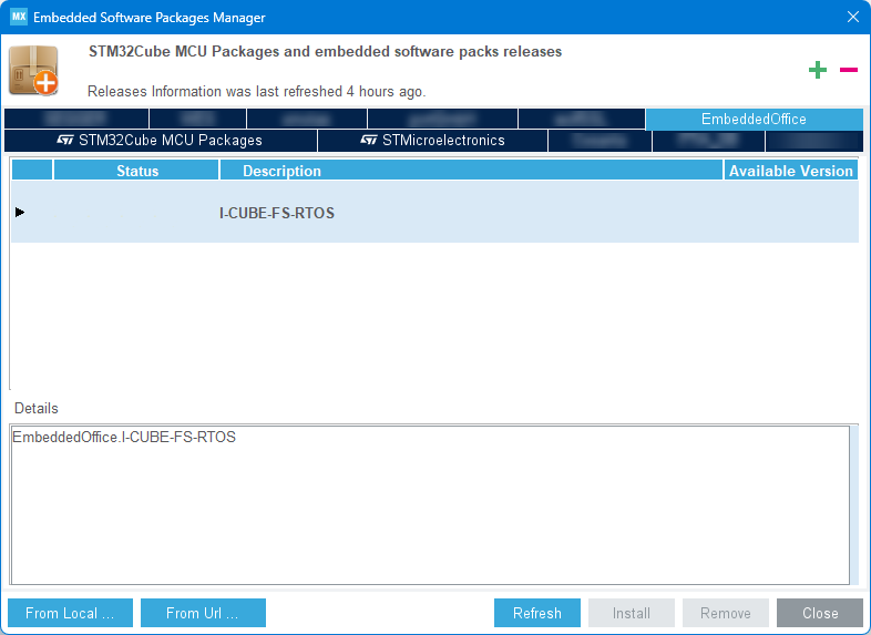
Resulting Installed Component: I-CUBE-FS-RTOS
Note: With the little arrow on the left side, you can drop down the list of installed versions and check the corresponding release notes in the “Details” area.
Using the Expansion Pack
Selecting the Flexible Safety RTOS
You should start your evaluation with the button ACCESS TO MCU SELECTOR and select your choosen device.
Warning
You can start your evaluation with the ACCESS TO BOARD SELECTOR, too. But some provided board support backages are not compatible with the Blinky demo application. In case of troubles, please fallback to selecting the MCU.
In the upcoming tab Pinout & Configuration, use the Dropdown
Software Packs > Select Componentsand look for the installed ComponentEmbeddedOffice.I-CUBE-FS-RTOS.Open the component dropdown and select the variant “Eval” for the component FS-RTOS, and select an Application, (e.g. “Blinky”). After clicking the button
Ok, the component is available for further configuration.
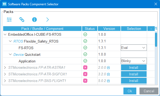
Selected Components: FS-RTOS & Demo Application Blinky
Note: If you see the small chip symbol in a component line, then this component does not support the microcontroller you have selected.
Hardware Settings
There are a few settings, you should check to get a working project:
Ensure the external crystal is used in
System Core > RCC > High Speed Clock.Ensure the system clock is set to a reasonable value in tab Clock Configuration (e.g. HCLK set to max).
In the generated application, the
SysTickis used as RTOS timebase. Therefore, the HAL should use a different source. You can achieve this by changing the HAL timebase source with:System Core > SYS > Timebase Sourcechange fromSysTickto …a. … another timer (e.g.
TIM1), or in case no timer is available:b. … disable the HAL timebase (selecting
None).Tip
If you disable the HAL timebase, you need to integrate the function call
HAL_IncTick();into the RTOS time tick handling by placing the function call into the callback functionApp_TimeTickHook()in fileBlinky/App/app_blinky_callbacks.c.You need to select and configure at least one GPIO output pin. This GPIO output pin is used in the application parameter settings.
Note
In the generated demo application we configure the important interrupt priorities to ensure a working system. If you navigate to System Code > SYS > NVIC for the first time, you will get a warning. You can just ignore this warning.
Configure the Flexible Safety RTOS
Back in the tab Pinout & Configuration, you will find the component I-CUBE-FS_RTOS in the category Middleware and Software Packs. We can start configuring it for the evaluation project:
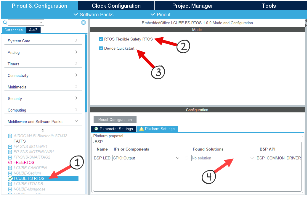
Configure FS-RTOS in 4 Steps
Select the Flexible Safety RTOS component: I-CUBE-FS_RTOS
Integrate the Flexible Safety RTOS in your project (there are no additional parameters to set)
Generate the selected demo application (e.g. Blinky)
You must specify an application-related selection of peripheral devices. This allows us to generate the required BSP functions. In the figure above, you must select the configured GPIO output pin for the LED.
Code Generation
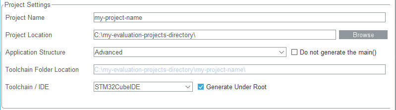
Finaly we perform some basic configurations for the code generation in the tab Project Manager.
Project Name: The name of your project directoryProject Location: The workspace directory, holding your project directoriesApplication Structure: Advanced (keep the Do not generate the main() unselected)Toolchain / IDE: Select toolchainSTM32CubeIDE(keep the Generate Under Root selected)
Considered Code Generation Settings
This is the setting which cover our needs; all other settings are left unchanged. You may change the settings on your preferences, but for the following description we consider these settings.
Project Structure
Well, with the Button GENERATE CODE (at the top right), you start the generation of the evaluation project. The STM32CubeMX generates the projects with a common structure:
+- <YourProjectName>                                 : your given project directory
|  +- Blinky                                         : selected demo application directory
|  +- Core                                           : microcontroller core source
|  |  +- Inc                                         : HAL interface include files
|  |  +- Src                                         : application initialization code
|  |  +- Startup                                     : microcontroller startup Code
|  +- Drivers                                        : hardware abstraction layer
|  +- Middleware                                     : middleware components
|  |  +- Third_Party                                 : ST Microelectronics partner
|  |  |  +- EmbeddedOffice_RTOS_Flexible_Safety_RTOS : Flexible Safety RTOS Eval Component
You find the Flexible Safety RTOS evaluation package in the ST defined directory tree, starting at Middleware and Blinky.
Note
The directory structure may differ slightly if you select other options on the generation tab in STM32CubeMX. But you will find the files in any case, just search for the given filenames.
RTOS Integration
When generating the project using the STM32Cube Expansion Pack, the complete Flexible Safety RTOS integration is already prepared. The following description is for your reference, or a simple guide in case you want to perform a manual integration into your existing project.
Time Tick Handling
The generated callback function file Blinky/App/app_blinky_callbacks.c we add the RTOS system tick handling:
void SysTick_Handler(void)
{
    OS_CPU_SR cpu_sr;            /* allocate space for interrupt nesting state */

    OS_ENTER_CRITICAL();         /* store state and disable interrupt nesting */
    OSIntEnter();                /* tell RTOS we are in an interrupt handler */
    OS_EXIT_CRITICAL();          /* return to stored interrupt nesting state */

    OSTimeTick();                /* RTOS time tick handling */

    OSIntExit();                 /* tell RTOS we are finished in this interrupt */
}
Note
Due to the evaluation configuration setting os/config:OS_TICKS_PER_SEC equal 1.000, the internal SysTick timer shall generate 1.000 system tick exceptions per second.
Diagnostics
Memory Exception Handling
If you change the demo and carry out experiments, you may encounter problems with memory exceptions. In this case, we recommend adding a small access error diagnosis to the generated project:
In the generated interrupt handler file Core/Src/<device>_it.c, add the collection of information about the access violation in the existing function MemManage_Handler():
/* Private includes ----------------------------------------------------------*/
/* USER CODE BEGIN Includes */

#include "app_blinky.h"

/* USER CODE END Includes */
    :
    :
void MemManage_Handler(void)
{
    /* USER CODE BEGIN MemoryManagement_IRQn 0 */

    SP_IsrHandler();              /* RTOS memory exception handling */

    /* USER CODE END MemoryManagement_IRQn 0 */
    while (1)
    {
        /* USER CODE BEGIN W1_MemoryManagement_IRQn 0 */
        /* USER CODE END W1_MemoryManagement_IRQn 0 */
    }
}
The access fault callback function generated in Blinky/App/app_blinky_callbacks.c is called with the collected information:
info->CurPrio: which task performs a memory violationinfo->IAddress: which instruction address occurs the exceptioninfo->DAddress: which data address is write protected
void SPAccessFaultEvent(SP_ACCESS_FAULT_T *info)
{
    OSTaskSuspend(info->CurPrio);        /* stop failing task */

    while(1) { }                         /* place here your error handling */
}
Tip
That is the whole RTOS integration we need for now. We are ready for diving deeper into the File Structure of the Flexible Safety RTOS component and start creating interesting experiments.